Precision Approaches
Objective
Timing
Format
Overview
- Precision Approach Types
- Localizer Principles of Operation
- Glideslope Principles of Operation
- Marker Beacons
- ILS Receiving Equipment
- ILS Categories
- ILS Errors and Irregularities
- Localizer and Glideslope Critical Areas
- Precision Instrument Approaches
- Back Course Approaches
- APV Instrument Approaches and GPS Approaches
Elements
Precision Approach Types
Precision approaches are characterized by vertical and horizontal guidance that positions the aircraft close to the runway.
- PAR - Precision approach radar
- GLS - GBAS landing system
- ILS - Instrument landing system
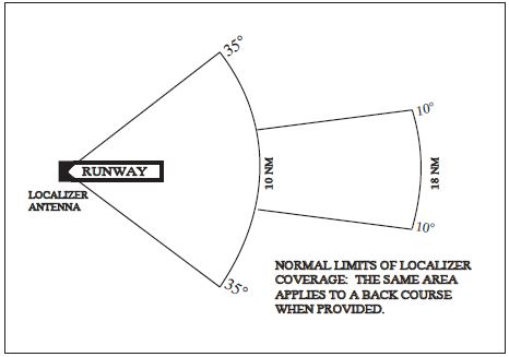
Localizer Principles of Operation
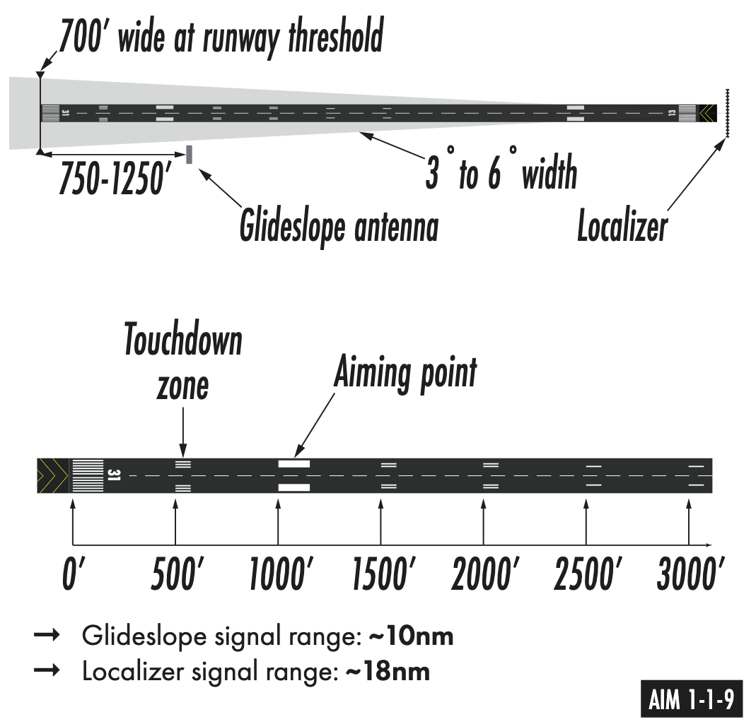
- Provides horizontal guidance along the extended runway centerline
- Transmitter located at the far end of the runway
- Operates on 40 channels within the 108.10 MHz to 111.95 MHz frequency range (odd tenths)
- Adjusted for a course width of 700 feet at the runway threshold
- Normal service volume extends to 18 NM within 10° of centerline and 10 NM within 35°
- Identification consists of a three-letter Morse code designator preceded by the letter "I"
- The morse code identifier is printed on approach and enroute charts
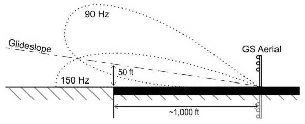
Glideslope Principles of Operation
- Provides vertical guidance toward the runway touchdown point
- Frequency is automatically paired with the localizer frequency
- Operates in the UHF frequency range between 329.15 MHz and 335.00 MHz
- Transmitter located 750 to 1,250 feet from the approach end and offset 250 to 600 feet from centerline
- Normally adjusted to a projection angle of 3° above horizontal
- Provides a usable signal to a distance of 10 NM
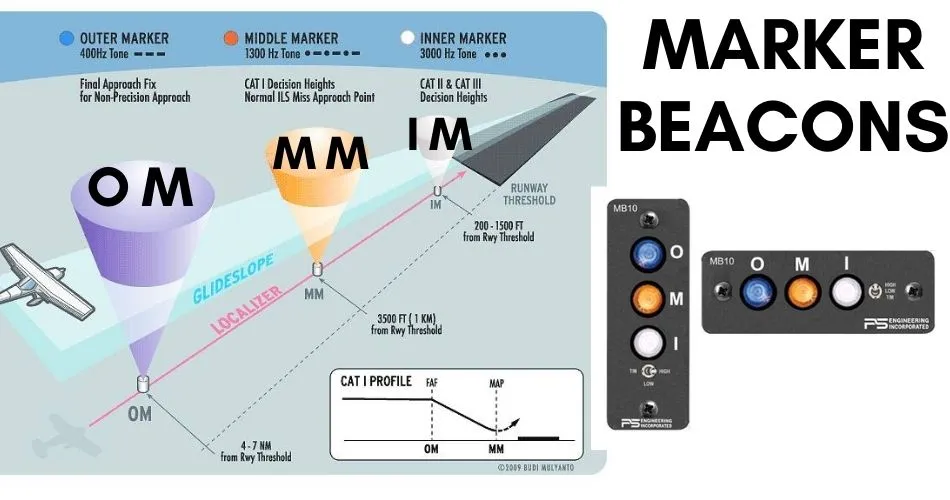
Marker Beacons
- VHF transmitters operating on 75 MHz to provide range information along the approach path
- Antenna array produces an elliptical pattern above the station
- Types of markers
- Outer Marker (OM): Located 4 to 7 miles out; indicates glidepath intercept point; blue light and low-pitch dashes
- Middle Marker (MM): Located ~3,500 feet from threshold; indicates ~200' altitude above threshold; amber light and alternate dots/dashes
- Inner Marker (IM): Indicates Decision Height for CAT II approaches; white light and high-pitch dots
- Back Course Marker: Indicates the final approach fix for a back course approach; white light and pairs of dots
- Markers beacons have mostly been decommissioned, except for inner markers required for CAT-III approaches at large airports. Per AIM 1-1-9, the following may be substituted for an outer marker:
- DME fix
- VOR or VOR intersection
- Suitable RNAV/GPS system
- NDB in certain scenarios
ILS Receiving Equipment
- Combined VOR/Localizer receiver with common tuning
- Navigation indicator includes localizer (vertical) and glideslope (horizontal) needles
- Warning flags (NAV, GS, or OFF) appear if signal strength is insufficient or equipment fails
- Audio switch panel used to monitor Morse code identifiers and marker beacon tones
- Selective sensitivity on some marker beacon receivers (usually on the audio panel)
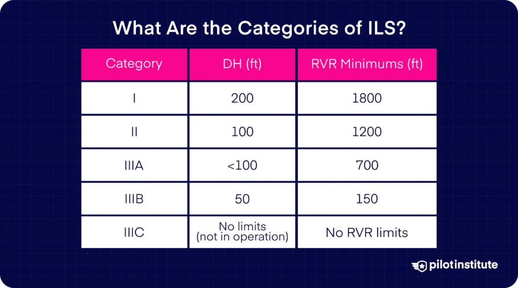
ILS Categories
- Category I: DH 200 feet and RVR 2,400 feet (1,800 feet with TDZ/CL lighting or HUD/Autopilot)
- Special Authorization CAT I: DH 150 feet and RVR 1,400 feet using HUD to DH
- Category II: DH 100 feet and RVR 1,200 feet (1,000 feet with special authorization)
- Special Authorization CAT II: DH 100 feet and RVR 1,200 feet with reduced lighting
- Category IIIa: No DH or DH below 100 feet; RVR not less than 700 feet
- Category IIIb: No DH or DH below 50 feet; RVR between 150 and 700 feet
- Category IIIc: No DH and no RVR limitation
ILS Errors and Irregularities
- Reflection: Surface vehicles or aircraft below 5,000 feet AGL may cause signal disturbances
- False glideslope:
- Inherent GS signals at higher vertical angles (typically 9°– 12°)
- Backcourse glideslope: A glideslope signal may also be received when flying the BC of an ILS; it should be ignored
- Needle "chasing" often results from poor planning or over-controlling
- Guidance anomalies may occur below 100' above the DA
- In this case it's best to fly a known good heading and maintain the established descent rate
Localizer and Glideslope Critical Areas
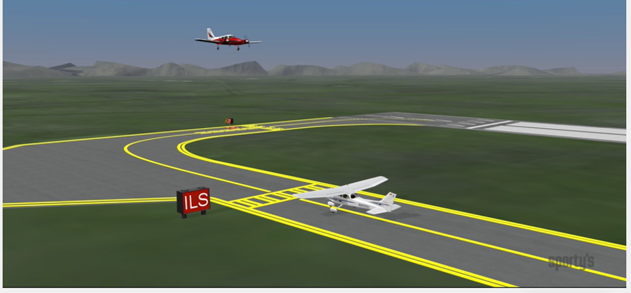
- Areas near antennas established to prevent signal interference by vehicles or aircraft
- ATC provides protection when ceiling is < 800 feet or visibility is < 2 miles
- Arriving aircraft inside the OM (or fix in lieu) triggers protection for both LOC and GS areas
Precision Instrument Approaches
- Requires pilot adherence to depicted altitudes, paths, and weather minimums
- GS should be captured from below the intercept altitude to avoid false courses.
- The Precise Final Approach Fix (PFAF) is the point of glideslope intercept at the published altitude
- Stabilized approach concept (constant rate and configuration) is critical below 1,000 feet AGL
- Descent rates exceeding 1,000 FPM are generally unacceptable on final
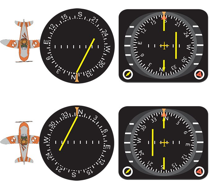
Back Course Approaches
- Approach using the localizer signal in the opposite direction of the front course
- Identified as "LOC BC" on approach charts
- Reverse sensing occurs on standard VOR indicators (fly away from the needle)
- HSI eliminates reverse sensing if set to the front course heading
- The HSI OBS should be set to the front course of the runway (180° off of aircraft heading)
- Glideslope is not provided; vertical guidance must be ignored if received
- For autopilot-coupled approaches, ensure it is configured to track a backcourse signal
APV Instrument Approaches and GPS Approaches
RNAV = Random Area Navigation
- RNAV Approaches with Vertical Guidance
- LPV - Localizer Performance with Vertical guidance
- ILS-like minimums (200' minima) and is flown similar to an ILS
- Gives L/R angular guidance, similar to an ILS
- Not technically a "precision approach" (for the purposes of alternate planning)
- LNAV/VNAV - Lateral/vertical navigation (Garmin L/VNAV)
- Final approach has fixed 0.3NM sensitivity (not angular like an ILS or LPV)
- Doesn't require a WAAS-based navigator
- These were initially design for baro-aided FMS systems
- LPV - Localizer Performance with Vertical guidance
- RNAV Non-precision approaches
- LP - Akin to a LOC approach
- LNAV - Lateral guidance
- GPS overlay approaches
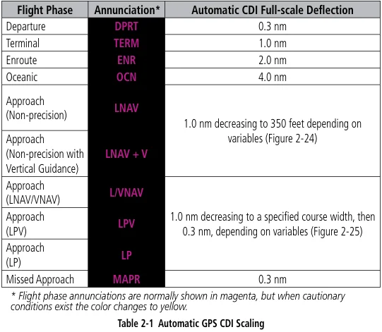
- GPS Sensitivity
- ENR, TERM, LNAV, LP
- Advisory Vertical Guidance (LP +V, LNAV+V)
- GPS units can provide advisory vertical guidance which meets the steps downs
- This approach still has an MDA however
References
- Instrument Flying Handbook: 9-35 to 9-43
- Aeronautical Information Manual: Chapter 1, Section 1; Chapter 5, Section 4; Chapter 5, Section 5
- TERPS Manual (FAA Order 8260.3): Chapters 1, 3, 10, and 12
- Pilot-Controller Glossary: 1952, 1954, 1975, 1984, 1986, 2041