IFR Cross-Country Planning, Symbology, and Reporting
Objective
The student will demonstrate the ability to utilize IFR planning publications and charts, interpret complex en route symbology, and adhere to mandatory position and status reporting requirements to maintain safety and separation in the National Airspace System (NAS).
Overview
- Chart Supplements
- En Route Low Altitude IFR Chart
- En Route Chart Symbology
- Air Traffic Service (ATS) Route System
- Intersections and Changeover Points
- ATS Route Course Changes
- Flight Deck Management
- Position Reporting Requirements
- Additional Reporting Requirements
- Loss of Communications Procedures (IMC and VMC)
Elements
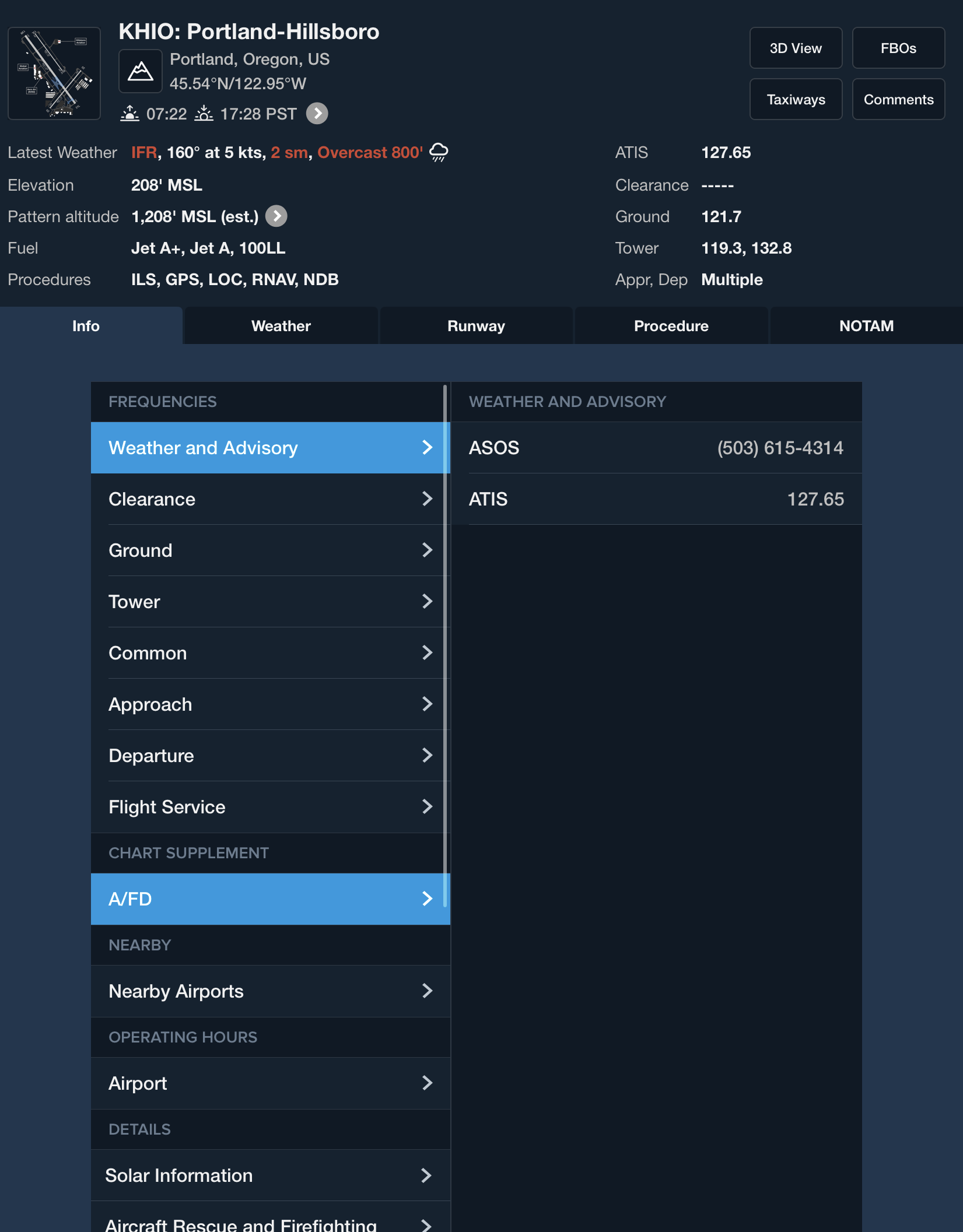
Chart Supplements
- Published by Aeronautical Information Services in regional booklets every 56 days
- Contains the Airport/Facility Directory (A/FD) with detailed data on public-use airports
- Includes runway dimensions, surface types, load capacities, and lighting codes
- Lists weather data sources, communication frequencies, and NAVAID status
- Features full-page airport diagrams and "Hot Spot" locations for complex layouts
- Provides Preferred IFR Routes and TEC route descriptions
En Route Low Altitude IFR Chart
- Provides aeronautical info for IFR navigation below 18,000 feet MSL
- Depicts Victor airways (VOR-based) and T-routes (RNAV-based)
- Shows limits of controlled airspace, VHF NAVAIDs, and reporting points
- Includes minimum en route altitudes (MEA) and obstruction clearance altitudes (MOCA)
- Contains OROCA for situational awareness and emergency use
- Charts are revised every 56 days
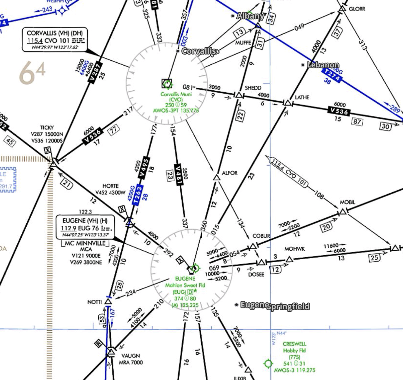
En Route Chart Symbology
- NAVAID boxes show name, identifier, frequency, and Morse code
- Compulsory reporting points depicted as solid triangles
- "On request" reporting points depicted as open triangles
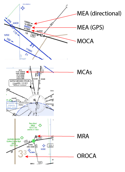
- MEA is the lowest altitude between fixes ensuring signal reception and obstacle clearance
- MOCA (preceded by *) ensures signal coverage only within 22 NM of a VOR
- MRA (preceded by symbol) is the lowest altitude to receive an off-course NAVAID to identify a fix
- MCA (preceded by symbol) is the altitude required to cross a fix when climbing to a higher MEA
| Altitude | Name | Obstruction Clearance | Navaid Signal |
|---|---|---|---|
| MEA | Minimum Enroute Altitude | ✅ | ✅ |
| MOCA | Minimum Obstruction Clearance Altitude | ✅ | Within 22nm (25 s.m.) of NAVAID |
| MCA | Minimum Crossing Altitude | ✅ | ✅ |
| MRA | Minimum Reception Altitude | ✅ | ✅ |
| MAA | Maximum Authorized Altitude | ✅ | ✅ |
| OROCA | Off-route Obstruction Clearance Altitude | ✅ | ❌ |
Air Traffic Service (ATS) Route System
- Generic term including VOR Federal airways, colored airways, jet routes, and RNAV routes
- Victor airways are identified by "V" and exist from 1,200' AGL up to 18,000' MSL
- Jet routes are identified by "J" and exist from 18,000' MSL to FL 450
- RNAV routes include Q-routes (high) and T-routes (low) depicted in aeronautical blue
- Standard airway width is 8 NM (4 NM each side of centerline)
- Routes are contained within Class E (low) or Class A (high) airspace
| Airway Type | Chart Type | Identifier Prefix | Altitude Range | Depiction Color | Primary Navigation Base |
|---|---|---|---|---|---|
| Victor Airways | Enroute Low Altitude | V | 1,200' AGL up to (but not including) 18,000' MSL | Black | VOR or VORTAC |
| T-Routes (RNAV) | Enroute Low Altitude | T | 1,200' AGL up to (but not including) 18,000' MSL | Aeronautical Blue | GNSS (GPS/WAAS) |
| Jet Routes | Enroute High Altitude | J | 18,000' MSL to FL 450 | Black | VOR or VORTAC |
| Q-Routes (RNAV) | Enroute High Altitude | Q | 18,000' MSL to FL 450 | Aeronautical Blue | GNSS or DME/DME/IRU |
| Y-Routes (RNAV) | High/Low Enroute (Offshore) | Y | Predominantly Class A offshore (>18,000' MSL) | Blue | GPS (RNAV 2) |
Intersections and Changeover Points
- Intersections are fixes formed by crossing VOR radials, DME, or RNAV waypoints
- Changeover Points (COP) specify where to switch navigation guidance from one facility to the next
- COP prevents frequency interference and ensures continuous signal reception
- Depicted as a "bent" line symbol on airways with a number indicating mileage from a fix
- If no COP is charted, the change should occur at the midpoint of the route segment
- PHOTO PLACEHOLDER: Chart example of a COP symbol and an intersection
ATS Route Course Changes
- Pilots required to adhere to airway/route centerlines
- Course changes require lead turns based on turn radius, wind, and airspeed
- Lead points ensure the aircraft remains within protected airspace boundaries
- Distance measuring equipment (DME) or RNAV used to determine lead points
- High-speed aircraft require more significant turn anticipation
Flight Deck Management
- Systematically cross-check GPS position against VOR or DME data
- Track actual time of arrival (ATA) and fuel state at each fix to monitor progress
- Keep interior lights low at night to preserve vision
Position Reporting Requirements
91.183: IFR Communications 91.187: Equipment malfunction reports
- Required over each compulsory point (solid triangle) when not in radar contact
- Required over each fix used in the flight plan for direct route flights
- Reports include:
- Identification
- Position
- Time
- Altitude
- Next fix, and ETA of cross next fix
- Actual altitude/flight level included when operating on a clearance specifying "VFR-on-top"
- Discontinue reports over compulsory points when informed of "radar contact"
- Resume reporting when advised "radar contact lost" or "radar service terminated"
Additional Reporting Requirements
The acronym STALLMUUVA is a common mnemonic used to remember the additional reports that pilots must make to Air Traffic Control (ATC) or Flight Service Stations (FSS) without a specific request while operating under Instrument Flight Rules (IFR).
The following breakdown explains each element of the acronym as defined in the provided sources:
| Letter | Component | Details |
|---|---|---|
| S | Safety of flight | Any information relating to the safety of flight must be reported at all times. |
| T | Time reaching fix | The time and altitude/flight level reaching a holding fix or point to which cleared. |
| A | Altitude change when VFR-on-top | When an altitude change will be made if operating on a clearance specifying "VFR-on-top". |
| L | Leaving holding fix | When leaving any assigned holding fix or point. |
| L | Loss of equipment | Any loss of navigation or communications equipment or capabilities. |
| M | Missed approach | When an approach has been missed, including a request for specific action. |
| U | Unable to climb/descend 500 fpm | When unable to climb or descend at a rate of at least 500 feet per minute. |
| U | Unforecast weather | Weather conditions which have not been forecast, hazardous forecast conditions |
| V | Variation in airspeed | Change in true airspeed when it varies by 5 percent or 10 knots (whichever is greater) from the flight plan. |
| A | Assigned altitude | When vacating any previously assigned altitude or flight level for a newly assigned one. |
Loss of Communications Procedures (IMC and VMC)
- If in VMC or if VMC is encountered, continue under VFR and land as soon as practicable
- If in IMC, follow route (AVE F) in order: Assigned, Vectored, Expected, Filed
- If in IMC, fly altitude (MEA) at the highest of: Minimum, Expected, Assigned
- If radio failure occurs while being radar vectored, proceed direct to the fix specified in vector clearance
- Leave clearance limit at the EFC time, or if none, at the ETA filed in flight plan
- Squawk 7600 to notify ATC of radio failure
References
- Aeronautical Information Manual (AIM): Chapters 1, 3, 4, 5, 6, 7, 9
- Instrument Flying Handbook (IFH): Chapters 1, 2, 5, 8, 9, 10
- Instrument Procedures Handbook (IPH): Chapters 1, 2, 3
- Title 14 Code of Federal Regulations (CFR): Parts 1, 61, 71, 91, 95, 97
- TERPS Manual (FAA Order 8260.3): Chapters 1, 2, 14, 16
- Pilot-Controller Glossary