Magnetic Compass
Objective
Review the magnetic compass construction, operation, errors, and usage under IFR. Also introduce timed turns and partial panel turns.
Timing
- 30 minutes
Format
- Whiteboard
Overview
- Magnetic Compass Construction
- Magnetic Deviation
- Magnetic Variation
- Magnetic Dip
- Northerly Turning Error
- Acceleration Error
- Oscillation Error
- Turns to Magnetic Compass Headings
- Emergency Alternatives to Magnetic Compass Turns
- Calibrating Turn Coordinator
- Timed Turns
Elements
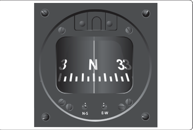
Construction
- An aircraft magnetic compass has two small magnets attached to a metal float sealed inside a bowl of clear compass fluid similar to kerosene. The buoyancy of the float takes most of the weight off the pivot
- A graduated scale, called a card, is wrapped around the float and viewed through a glass window with a lubber line across it
- This jewel-and-pivot type mounting allows the float freedom to rotate and tilt up to approximately 18° angle of bank
- The compass card stays stationary, and the pilot turns around it
- Oscillation errors: Erratic movement of the card caused by turbulence or rough control inputs
Magnetic Deviation
- Magnetic fields caused by aircraft electronics and wiring can affect the magnetic compass
- This induced error is called compass deviation
- The compass card in your airplane will show the error
- Note: electronic heading indicators will internally compensate for magnetic deviation
Magnetic Variation

- The location of true north (geographic north), and magnetic north are not the same place.
- Magnetic north also changes over time as the Earth's magnetic field changes
- Magnetic variation is the error caused by the difference between true and magnetic north
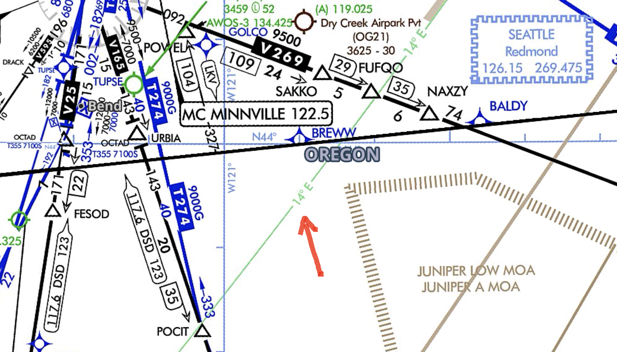
- Corrected by isogonic lines, or lines of equal variation
- These are dashed magenta lines on a sectional, bright green lines on an IFR enroute chart
- Agonic Line: The line along which the two poles are aligned, and there is no variation
- Correcting for magnetic variation
- True course ± variation = magnetic course
- Remember: East is Least, West is Best
- Subtract easterly variations to get a magnetic heading
- Add westerly variations to get a magnetic heading
Dip Errors
- Acceleration errors: On east or west heading, the compass will show a
momentary turn to the north when accelerating, and to the south when
decelerating.
- Accelerate
- North
- Decelerate
- South
- Northerly turning errors: On north or south headings, the compass will lead
in the north half of the turn, and lag in the south half of the turn.
- Undershoot
- North
- Overshoot
- South
Turns to Magnetic Compass Headings
- A northerly turn should be stopped prior to arrival at the desired heading
- One rule of thumb to correct for this leading error is to stop the turn 15° plus half of the latitude (e.g. 15 + (45/2) = 15 + 22.5 = 37.5°)
- A southerly turn, the aircraft should be allowed to pass the desired heading prior to stopping the turn
Timed Turns
- A standard rate turn in 2 minutes for a 360° turn, or 60 seconds for a 180° turn
- This is a turn rate of 3° per second
- E.g., 45-degree turn: 15 seconds
- Instruments during a timed turn
- Bank: Mini aircraft (turn coordinator)
- Pitch: Altimeter
- Power: Airspeed Indicator
- How to make a timed turn
- Smoothly enter a standard rate turn and start the clock (alternatively you can wait until the second hand passes a cardinal point on the clock)
- Maintain your scan and crosscheck for bank, airspeed, attitude
- Start your rollout when the time expires, cross-check your heading indicator
- Partial-panel timed turn
- No heading or attitude indicator to reference
- Turn coordinator still primary instrument; cross-check altimeter/VSI/ASI for pitch
- Check magnetic compass after the completion of the turn
Turn Coordinator Calibration
- Prior to performing timed turns, calibrate the turn coordinator to determine its accuracy
- Note heading & start a standard rate turn as the second hand passes a cardinal direction (12, 3, 6, 9)
- Hold standard rate and note heading changes every 10 seconds (should be 30o of turn)
- If the amount of turn is more or less than 30o, adjust bank to obtain standard rate
- Check the standard rate bank in both directions, use the corrected bank angle for all timed turns
References
- Instrument Flying Handbook pg. 5-10
- Backseat Pilot CFI-I Lesson Plans: VI.F. Timed Turns to Magnetic Headings