Flight Instruments
Objective
Review the pitot-static and gyroscopic instruments, their operation and errors, and emphasize how they are relied upon for IFR flight.
Timing
45 minutes
Format
- Whiteboard
- Pitot Static System Simulator
Overview
Elements
Pitot-Static Instruments

- Pitot: Pitot tube, often on the wing of GA aircraft
- Static port: Usually flush with the fuselage on the side of an aircraft
- Which instruments are pitot static instruments?
Altimeter (Sensitive altimeter)

- Static ports
- Fed by one or more static ports on the side of the aircraft
- Some static ports may be heated
- A traditional altimeter contains an aneroid wafer with a vacuum inside
- As ambient pressure changes, the wafer expands and contracts
- This expansion causes the needle to move up/down
- 1” Hg = 1,000’
- Types of altitude
- Indicated altitude: Read from the altimeter
- True altitude (MSL): How many feet the aircraft is above true mean sea level
- Pressure altitude: Read from the altimeter when set to 29.92"
- Also, the height in the standard atmosphere where that ambient pressure would be found
- Density altitude
- The height in the standard atmosphere where an equivalent pressure is found after adjusting for non-standard temperature and pressure
- Absolute altitude (AGL): Actual height above the terrain
- Altimetry errors
- Cold weather errors: Cold air is more dense, therefore at the same indicated altitude the aircraft would be flying lower than is indicated
- Think of the cylinder of air below the aircraft condensing in cold weather
- Warm weather errors: Warm air is less dense, therefore at the same indicated altitude the aircraft would be flying higher than is indicated
- Think of the cylinder of air below the aircraft expanding in hot weather
- Ambient pressure errors: Altimeters also need to be set to a nearby altimeter setting to account for changes in ambient pressure
- Flying from high to low pressure: Altimeter will indicate higher than true altitude
- Flying from low to high pressure: Altimeter will indicate lower than true altitude
- Altimeter should read within 75 feet of the airport elevation (AIM 7-2-3)
- "From hot to cold, or high to low, look out below"
- Cold weather errors: Cold air is more dense, therefore at the same indicated altitude the aircraft would be flying lower than is indicated
Simulation Scenario
From high to low pressure
- Set to 9000' and 120 knots
- Manually set altimeter to 29.92
- Change pressure to 29.45
- Note altimeter reads 400' high (this would make us fly 400' lower)
From hot to cold temperature
- Set to 9000' and 120 knots
- Manually set temperature to -10°
- Note altimeter reads 300' high (this would make us fly 300' lower)
Blocked static source
- Set to 9000' and 120 knots
- Block static source
- Climb to 9500', note airspeed drop and altitude doesn't change
Alternate static source
- Set to 9000' and 120 knots
- Block static source
- Enable alternate static source
- Note slight increase in altitude and airspeed (lower pressure in alt. static air)

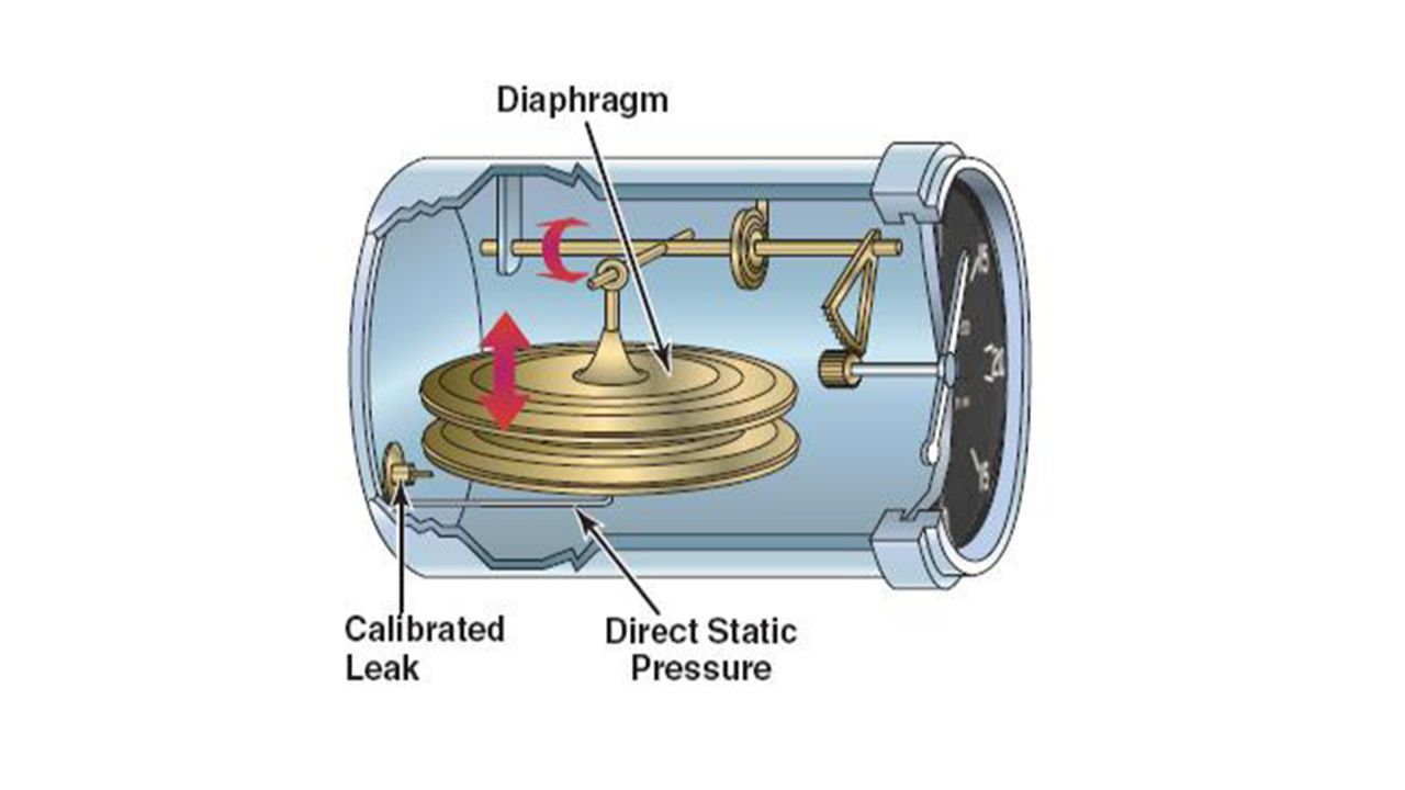
Vertical Speed Indicator
- Uses a diaphragm similar to an ASI, with static pressure on one side and instrument case pressure on the other
- The instrument case has a "calibrated leak" which prevents the case from changing pressure too quickly
- Thus, the diaphragm changes immediately relative to the case pressure, which changes slowly
| Operation | Static Pressure | Diaphragm | VSI Indication |
|---|---|---|---|
| Climb | Decreases | Pressure decreases, contracting the diaphragm | Indicates a climb |
| Descent | Increases | Pressure increases, expanding the diaphragm | Indicates a descent |
Airspeed Indicator

Airspeed = (RAM air pressure - static pressure)
- Operation
- Pitot Tube: Diaphragm
- Static Port: Instrument Case
- Types of Airspeed
- Indicated airspeed: Read from the altimeter
- Calibrated airspeed: Airspeed corrected for installation and position errors
- True airspeed: The speed at which the aircraft is moving through the airmass
- Changes in temperature and ambient pressure result in different air densities
- This means the aircraft could be moving faster or slower through an airmass at the same indicated airspeed
- True airspeed corrects for this
- Pitot-static errors and malfunctions
- Blocked pitot tube (drain tube free): Indicated airspeed slowly drops to zero
- Blocked pitot tube (drain tube blocked): Indicated airspeed drastic increases as the aircraft climbs, and decreases as it descends
- Blocked static port: Altimeter will read altitude where it became blocked
- Alternate static source: Used for situation where the static port becomes blocked
- Pressure inside the cabin is lower than the pressure on the outside of the fuselage
- Altimeter reads slightly higher than actual
- Airspeed reads slightly faster than actual
- Pressure inside the cabin is lower than the pressure on the outside of the fuselage
Static Simulation Scenario
Ram blockage blockage
- Set to 9000' and 120 knots
- Block ram air tube
- Note airspeed
Ram + drain blockage
- Set to 9000' and 120 knots
- Block RAM and drain tube
- Note airspeed
- Climb to 9500 and note airspeed
- Descent to 8500 and note airspeed

Gyroscope Instruments
A spinning object exhibits the following qualities:
- Rigidity in space
- Precession
Gyroscopic instruments are often powered by:
- An electric motor
- Pneumatic systems: Venturi tubes or vacuum pumps
- Wet-type vacuum system: Engine-driven steel vane air pump
- Lubricated with engine oil
- Often used with smaller, lower-flying aircraft
- Dry-air vacuum pump
- Oil is not mixed with the air (hence dry)
- More suitable for higher-altitude operations where the air is thinner
- Wet-type vacuum system: Engine-driven steel vane air pump

Attitude Indicator
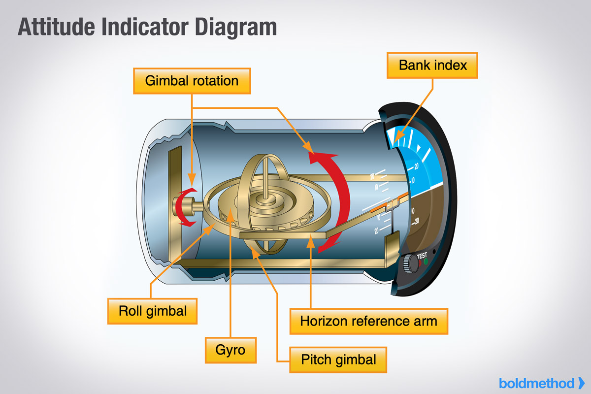
- Sometimes called an "artificial horizon"
- Operation
- Contains a vertical spinning wheel, spun at high speeds
- This wheel is mounted in a double gimbal, which allows the aircraft to pitch and bank around the gyro
- Older instruments have pitch/bank limits at which the gyro tumbles, becoming unreliable
- Gyroscopic A.I.'s can take up to 5 minutes to stabilize
- Some AI's have a slight acceleration error
- Slight nose-up indication when accelerating
- Slight nose-down indication when decelerating
Gyro-driven Heading Indicator

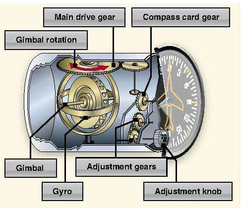
- Operation
- Mounted in double gimbal axis (like the attitude indicator), but the spin axis is horizontal
- Headings turn cause rotation around the aircraft's vertical axis
- These are not compasses and are not north-seeking
- They must be periodically set to the magnetic compass
- The Earth constantly rotates at 15° per hour, and the gyro is rigid in space
- Thus, the heading error will accumulate at least at 15° per hour
- Standard practice is to compare the compass and HI every 15 minutes
Remote Indicating Compass/Radio Magnetic Indicator (RMI)
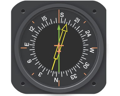
- A flux valve automatically adjusts heading as you turn
- Flux valve (pictured right): small, segmented ring of soft iron that readily accepts lines of magnetic flux. As heading changes, current in the flux valve changes, rotating the RMI’s heading
- Bearing indicator(s) overlaid on a heading indicator
- Doesn't require constant calibration like a heading indicator
- Gyro automatically "slaves" to the detected heading
- These can usually operate in "slave" or "free gyro" mode
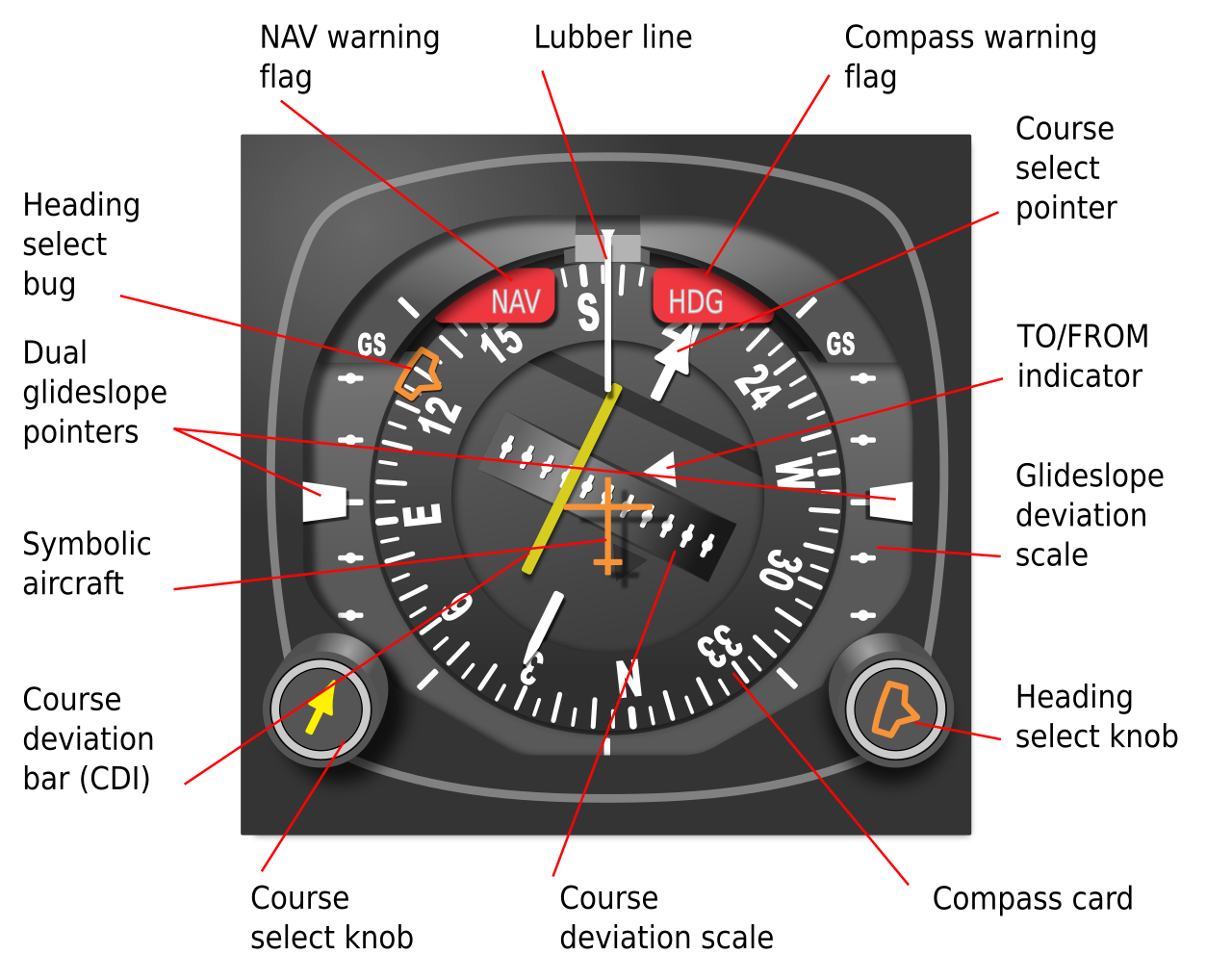
HSI
- Operates just like an RMI, but overlays a CDI and glideslope
Turn-and-Slip Indicator
- Operation
- Operates in much the same way as the heading indicator with a vertical spinning gyro
- Unlike an AI or HI, it only has a single gimbal
- Yawing produces a force in the horizontal plane
- Precession causes the gyro and its gimbal to rotate about the gimbal axis
- Used to make standard-rate turns
- Often are powered by a DC motor, for redundancy if the main vacuum pump were to fail
Turn Coordinator
- Improvement over a basic turn-and-slip indicator
- Operates like the Turn and Slip Indicator, but the gimbal frame is angled up about 30°
- Allows it to sense both roll and yaw
- Since turns are done by roll and yaw, provides more accurate indication in initial stages of the turn
Slip/Skid Indicator
- Also called a coordination ball or inclinometer
- The inclinometer in the instrument is a black glass ball sealed inside a curved glass tube that is partially filled with a liquid for damping
- Indication in a left turn
- Ball centered: Coordinated, rate of turn rate aligned with bank
- Ball inside the turn: Slipping, rate of turn not enough for bank
- Ball outside the turn: Skidding, rate of turn too great for bank
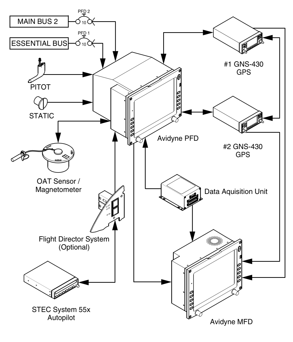
Electronic Flight Instruments
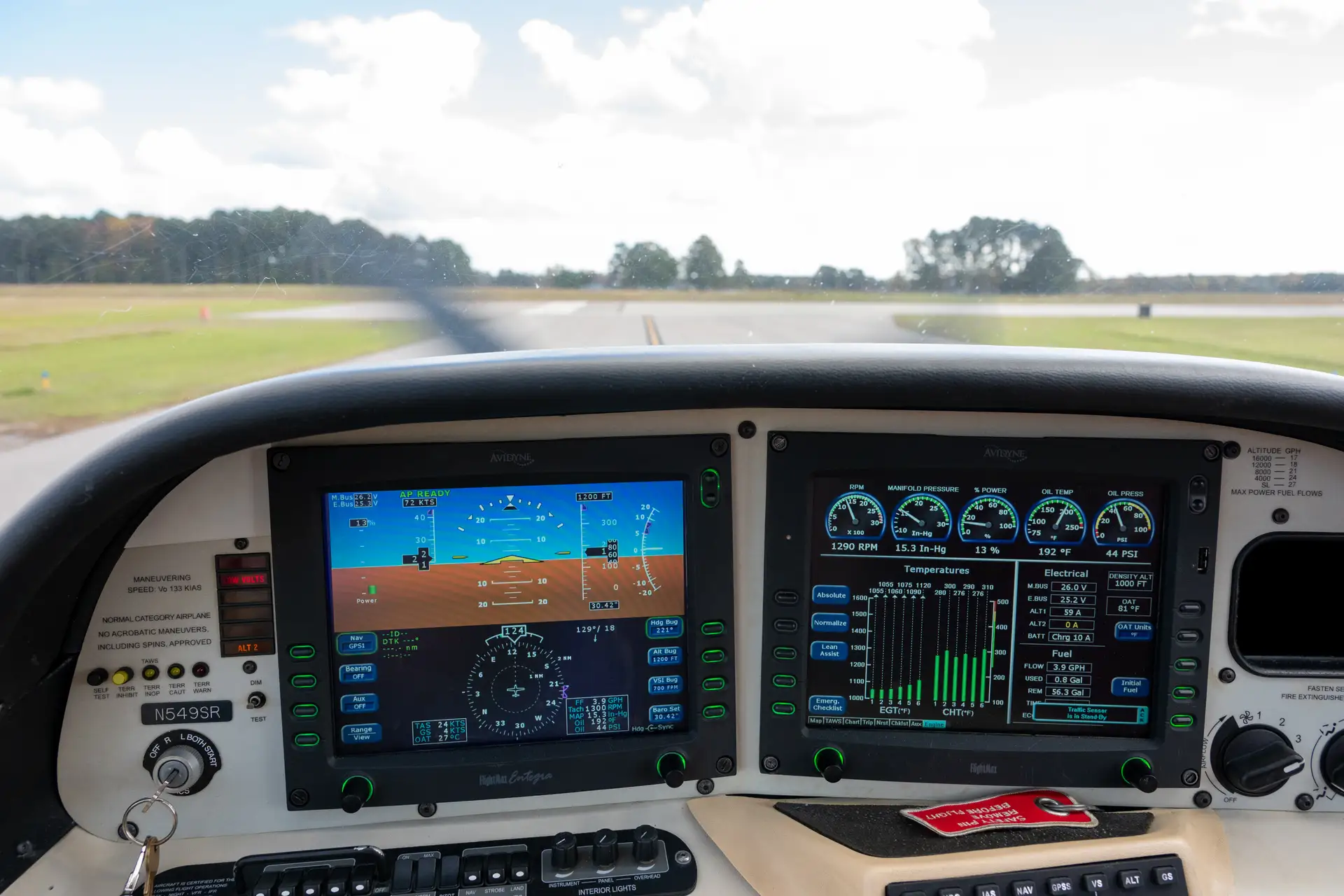
- Electronic Flight Information System (EFIS): Digital cockpit information display
- Primary flight display (PFD)
- Multi-function display (MFD)
- These are fed by various sub-systems
- AHRS: Attitude and Heading Reference System (AHRS)
- ADC: Air Data Computer: Processes pitot/static pressure and temperature information
- Magnometer: Electronic compass
- Computes airspeed, true airspeed, altitude, vertical speed
- Feeds an electronic flight information display (EFIS)
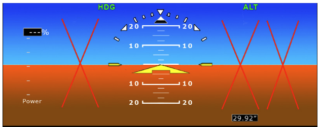
Primary Flight Display (PFD)
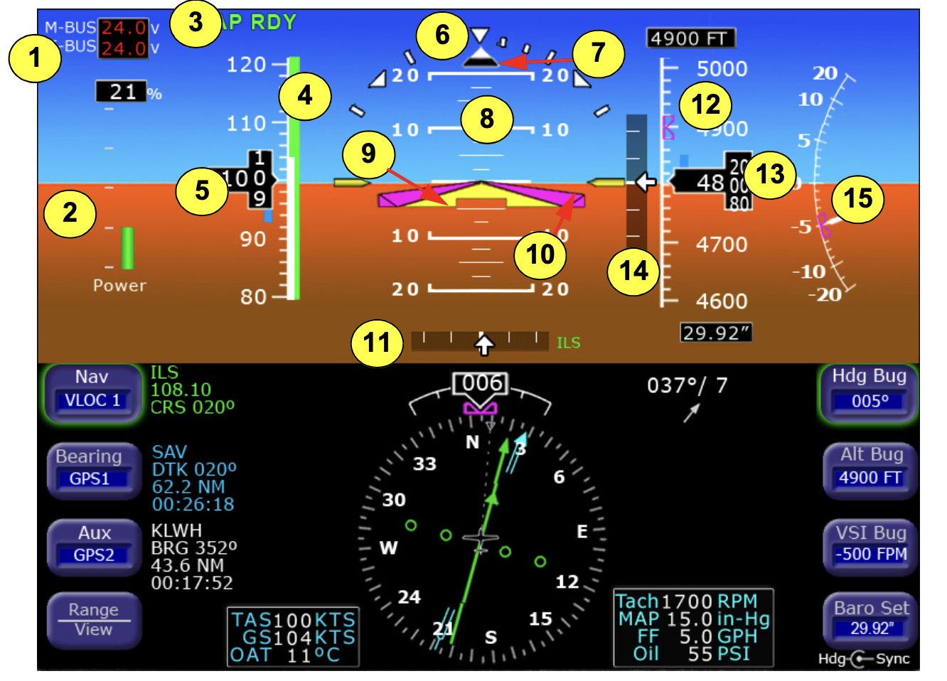
- Failure of components typically result in a red-X over the affected instrument
Multi-Function Display
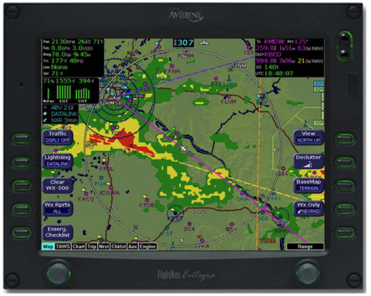
- Multi-function displays usually consist of a moving map, flight plan, terrain, and engine instrumentation
References
- Pitot Static System Simulator
- Instrument Flying Handbook pg. 5-1
- Backseat Pilot CFI-I Lesson Plans II.A.1