Instrument Approach Basics
Format
- Whiteboard
- Example approach charts
Objective
Develop an understanding of the common structure of an instrument approach procedure, and show how an approach chart describes that structure and information.
Timing
60 minutes
Outline
- What is an instrument approach?
- What are the common elements of an instrument approach?
- Instrument approach charts - Non-precision approach
- Margin information
- Briefing strip
- Plan view
- Profile view
- Minimums
- Precision approach
- How do we brief an approach
Content
What is an instrument approach?
An instrument approach is a procedure which can be used to place the aircraft in a position from where it can land at an airport.
Enroute phase > arrival phase > approach phase > landing
Two broad categories of approaches: Approaches with vertical guidance, approaches without vertical guidance
Structure of an IAP
- Transition routes, how do we get established on the approach
- Final approach segment with some kind of navigational guidance (ILS, VOR, GPS)
- Decision point: A point where we decide whether we are going to continue to land
- Dictated by a set of minimums, which tells us the altitude and visibility we need to have the runway in sight, and be able to land safely
- Also a set of criteria to ensure we can land safely
- Missed approach procedure with a hold
Chart Components
Non-precision approach example: KCVO VOR RWY 17

- Margin identification
- City/State (top L)
- Identifier and responsible agency (top C)
- Last update date (top R)
- Volume ID of TPP, effective dates (left C)
- Procedure title (bottom R)
- Typically with name of runway ILS 31
- "VOR-A": Not aligned with a runway
- RNAV 31 Z, Y: Multi approaches
- Airport name (bottom R)
- Briefing strip
- Primary navaid: Frequency and channel (military user)
- RNAV approaches will also have "WAAS" here for LP/LPV
- Approach course: Magnetic course, altitude, distance
- Runway length: 5100
- Touchdown zone elevation: TDZE
- Airport elevations
- Procedure notes:
- Non-standard takeoff mins
- Non-standard alternate mins
- What if there's an acronym here you don't recognize? TPP legend
- Missed approach procedure
- Frequencies
- Star next to com frequency: Indicates part-time tower ops
- Inverse L: Pilot controlled lighting
- Primary navaid: Frequency and channel (military user)
- Planview
- IAF: Initial approach fix, where the approach can be start
- IF: Intermediate fix - indicates we are on intermediate segment, aligned with the runway
- MSA: Minimum safe altitudes, for emergencies (+1000' clearance over all obstructions)
- Obstruction: +/- means "doubtful accuracy"
- "RADAR REQUIRED"
- Marker beacon: Outer, middle, and inner
- Profile view
- Approach descent angle: 3.2, TCH = Threshold crossing height
- FAF: Maltese cross
- Missed approach point: For non-precision it is the last waypoint
- VDP: V symbol near the runway, point at which the approach descent angle from the touchdown zone intercepts the MDA
- Airport sketch
- Lighting systems
- See Approach Lighting Systems
- MALSR: Medium-intensity approach lighting system
- V = VASI
- A5 = 5 lead-in strobes
- Inverted V and A5 = pilot controlled lighting
- Timing stable for different ground speeds
- Used for timing the missed approach point
- Lighting systems
- Landing minimums
- Airport categories: VREF or 1.3 * VS0
- A: Less than 91 knots
- B: 91 knots - 120 knots
- C: 121 knots - 140 knots
- D: 141 knots - 165 knots
- E: 166 knots or more
- See TPP supplement pg. 4 for category speeds
- "S-ILS 33L" - Straight in for 33L
- Altitude and visibility requirements
- Big numbers:
- Minimum descent altitude (MDA) or decision altitude (DA)
- Minimum visibility in s.m.
- RVR in 100's of feet, can be converted to s.m. (TPP supplement pg. 5) - See KSLE RNAV 31 for RVR
- Small numbers: MDA/DA in height about runway threshold
- Big numbers:
- Airport categories: VREF or 1.3 * VS0
Visual Descent Points (VDPs)
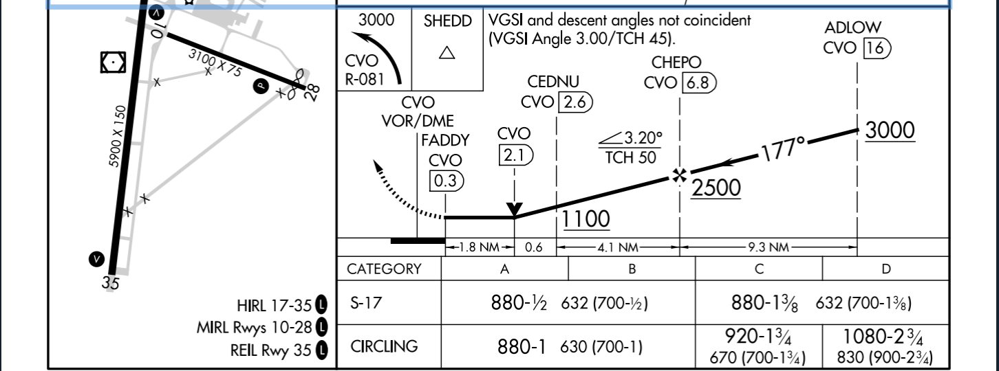
- Used on non-precision approach charts
- Tells you the last point where a descent to the runway can be made at the established (often, but not always, aligning with the angle of the PAPI/VASI)
- For 3° slope: (Minimum descent height) / 300 = Distance in nm to VDP
- Example: KCVO VOR 17
- VASI 3° angle: (632 MDH) / 300 = 2.1nm
- Approach angle 3.2°: (632 / 354) = 1.8
- Depending on our aircraft, we should treat the VDP as the MAP
- A 172 may be able to make a safe approach and landing at >3° descent angle
- A Cirrus or a King Air should probably make a missed approach
- Reminder that we need to land using normal maneuvers
Other Approach Charts
Precision approach: KMFR ILS or LOC RWY 14

Procedure turn: KSPB VOR-A

Hold-in-lieu of procedure turn: KSLE RNAV 31

Briefing an approach
Basic flow: Top left to bottom rate of the chart Example: KSLE RNAV 31, DIYAT to NECIP, LPV
W-WIRE: Weather, waypoints, instruments, radios, everything else
- Confirm approach name and chart currency
- NAVAIDs: Tune and identify
- Landing distance available, TDZE, airport elevation
- Procedure notes: Inoperative equipment
- Approach lighting system
- Tune COM frequencies
- Brief procedure entry
- Set procedure course in OBS
- Describe the procedure turn or hold-in-lieu of procedure turn
- Initial altitude restrictions
- Brief minimums for approach speed
- Missed approach procedure
- Any questions?
References
- DTPP Supplement: In ForeFlight FAA documents drive
- Instrument Flying Handbook pg. 10-13