1982 Cessna T182 Deep Dive
The following is a detailed exploration of a specific aircraft model based on information from the POH, TCDS, and other resources.
Source materials:
Aircraft Information
Powerplant
- Engine Manufacturer: Avco Lycoming
- Engine Model Number: 0-540-L3C5D
- Horsepower: 235
- Certificated Maximum Operating Altitude: 20,000 Ft
Induction system
- Air induction
- After passing through the turbocharger, the compressed air is ducted through the carburetor and induction manifold into the engine cylinders.
- Heated intake air may be obtained from a shroud which covers the exhaust manifold located on the left side of the engine, controlled by the carburetor heat control
- Cooling
- Cooling air is directed around the cylinders by baffling and through the remote oil cooler, then exhausted through cowl flaps on the lower edge of the cowling
- Before starting the engine, throughout takeoff and high power operations, the cowl flap lever should be open to provide maximum cooling
Turbocharger
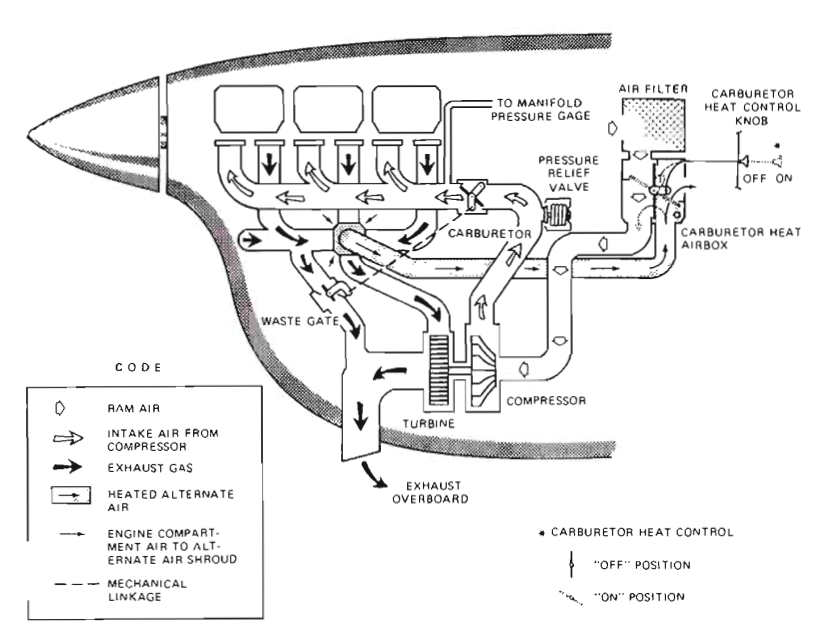
- The exhaust manifold discharges the gas into the turbine section of the turbocharger.
- A waste gate incorporated into the exhaust manifold, controls the volume of gas flowing through the turbine by venting excess gas through a bypass.
- Exhaust gases drive the turbine which, in turn drives the compressor
The compressor has the capability of producing manifold pressures in excess of 31 inHg. In order not to exceed the maximum, manifold pressure should be monitored closely and the throttle control adjusted as necessary to maintain 31 inHg.
Full open throttle control will not be necessary to maintain maximum continuous power (31 in. Hg.), with the possible exception during hot day conditions at high altitude.
- The turbocharged engine will react just the opposite of a normally aspirated
engine when the RPM is varied:
- When the RPM is increased, the manifold pressure will increase slightly
- When the RPM is decreased, the manifold pressure will decrease slightly
- Manifold pressure will also change slightly with airspeed:
- As airspeed is increased, the manifold pressure will increase slightly
- As airspeed is decreased, the manifold pressure will decrease slightly
- Manifold pressure will also change with mixutre:
- Enrichening the mixture will increase the manifold pressure
- Leaning the mixture will decrease the manifold pressure
Overboosting
An inadvertent overboost of 2 to 3 inches of manifold pressure is not considered detrimental to the engine as long as it is momentary. Immediate corrective action is required when an overboost occurs.
Propeller
Aircraft is equipped with a McCauley 3-blade, constant speed propeller.
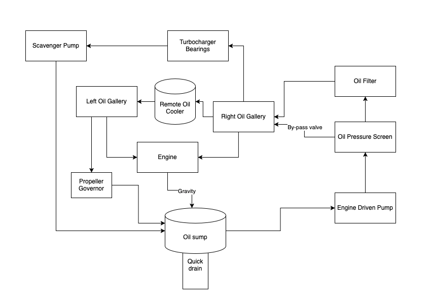
The propeller's pitched is controlled by a propeller governor, which controls flow of engine oil (boosted to high pressure by the governing pump) to or from a piston in the propeller hub.
- Oil pressure acting on the piston twists the blades toward high pitch / low RPM.
- When this oil pressure is relieved, centrifugal force, assisted by an internal spring, twist the blades toward low pitch / high RPM.
Fuel
- 100LL Fuel
- Two wing fuel tanks, 46 gallons each. 92 gallons total
- 88 gallons usable
- Fuel is delivered from the fuel system to the carburetor by gravity flow, the engine-driven fuel pump, and/or auxiliary fuel pump
- The fuel primer is a small pump which draws fuel from the fuel strainer when the plunger knob is pulled out, and injects it into the engine intake ports when the knob is pushed back in
- If a fuel tank quantity is completely exhausted in flight, it is recommended that the fuel selector valve be switched back to the BOTH position as this will allow some fuel from the fuller tank to transfer back through the selector valve to the empty tank
Oil
- Sump: 8 quarts
- Total: 9 quarts (an additional quart in the oil filter)
Engine Indications
- Tachometer
- Normal operating range: 2100-2400 RPM, 2400RPM red line
- Manifold Pressure
- Normal operating range: 17-25 inHg, 31 inHg red line
- Oil temperature
- Normal operating range: 100° - 245°F, 245°F red line
- Cylinder head temperature
- Normal operating range: 200° - 500°F, 500°F red
- Fuel pressure
- Normal operating range: 3.0 - 30.0 psi, 30.0 psi red line
- Oil pressure
- Normal operating range: 60 - 90 psi, 115 psi red line
Electrical System
The airplane is equipped with a 28-volt, direct-current electrical system.
There are two buses:
- The primary bus, which operates the fuel pumps, lights, and ignition switch
- The avionics bus, which operates the radios and other avionics
The master switch is a split-rocker type switch labeled MASTER, and is ON in the up position:
- The right half of the switch, labeled BAT, controls all electrical power to the airplane
- The left half, labeled ALT, controls the alternator
The ammeter, located between the fuel gages, indicates the amount of current, in amperes, from the alternator to the battery or from the battery to the airplane electrical system.
- In the event the alternator is not functioning or the electrical load exceeds the output of the alternator, the ammeter indicates a discharge
- There is also a LOW VOLTAGE indicator light on the right of the panel
- In the event of an over-voltage condition, the alternator will be
automatically removed from the electrical system
- The ammeter will then indicate a discharge from the battery
- The alternator can be reset by cycling the master switch
Weight Limits
- Max ramp weight: 3112 lbs
- Max takeoff weight: 3100 lbs
- Max landing weight: 2950 lbs
Load Factor Limits
- Flight Load Factors:
- Flaps Up: +3.8g, -1.52g
- Flaps Down: +2.0g
The design load factors are 150% of the above, and in all cases, the structure meets or exceeds design loads.
Flap Limitations
- Approved Takeoff Range: 0° to 20°
- Approved Landing Range: 0° to FULL
Speeds
Vr | 50 KIAS | Rotation Speed |
Vy | 87 KIAS | Best rate of climb, S.L. |
Vx | 73 KIAS | Best angle of climb, S.L. |
VS0 | 40 KIAS | Stall speed, flaps extended, bottom of white arc |
VS1 | 48 KIAS | Stall speed, clean configuration, bottom of green arc |
1.3 * VS0 | 52 KIAS | 1.3 * VS0 used as a reference for landings |
Va | At 3100 lbs: 111 KIAS At 2600 lbs: 101 KIAS At 2100 lbs: 90 KIAS | Maneuvering speed |
Vno | 140 KIAS | Normal operating speed, bottom of yellow arc |
Vne | 178 KIAS | Never exceed speed, red line |
Vfe | 140 KIAS for flaps 10° 95 KIAS for remaining flags | Flaps extended speed, top of white arc |
Vbg | Flaps up: 75 KIAS Flaps down: 70 KIAS | Best glide speed |
| Max crosswind landing | 15 knots |
Normal Procedures
Taxi
Normal takeoff
- Carburetor heat: cold
- Flaps 0° to 20°
- Power 31 inHg, 2400 RPM
- Rotate at 50 KIAS
- Climb speed 70 KIAS (flaps 20), 80 KIAS (flaps 0)
Normal climb
- Power 25 inHg, 2400 RPM
- Airspeed: 90-100 KIAS
- Mixture: full rich
- Cowl flaps: open (or as required)
Max performance climb
- Power 31 inHg, 2400 RPM
- Airspeed: 87 KIAS
- Mixture: full rich
- Cowl flaps: full open
Cruise
- Power 17-25 inHg, 2100-2400 RPM
- Carb heat: as required to prevent icing
- Mixture: leaned
- Cowl flaps: closed, or as required
Descent
- Power: as required
- Mixture: leaned for smoothness
- Cowl flaps: closed, or as required
- Wing flags: as desired (flaps 10° below 140 KIAS for speed reduction)
Landing
- Fuel selector: both
- Mixture: full rich
- Propeller: full fine
- Carb heat: on
- Airspeed: 70-80 KIAS (flaps up)
- Airspeed: 60-70 KIAS (flaps down)
- Lower nose wheel gently after touchdown
- After landing
- Carb heat: off
- Flaps: retract
- Cowl flaps: open
Go-around
- Power: 31 inHg and 2400 RPM
- Wing flaps: retract to 20°
- Climb speed: 60 KIAS until obstacles cleared
- Cowl flaps: open
- Power: Reduce to 25 inHg after obstacles cleared
Emergency Procedures
Spin Recovery
- Throttle to idle
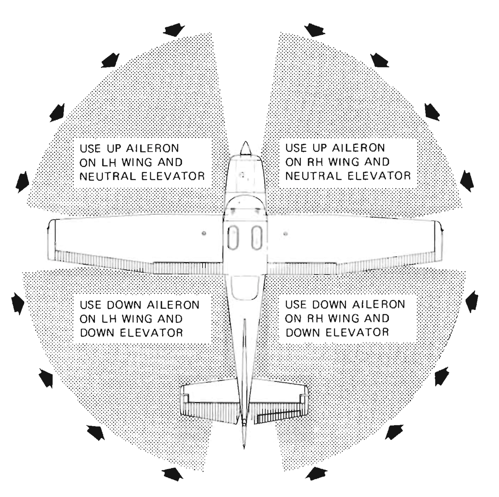
- Ailerons neutral
- Hold full opposite rudder until rotation stops
- Briskly push elevator control forward to break stall
- Hold until rotation stops
- Make a smooth recovery to level flight
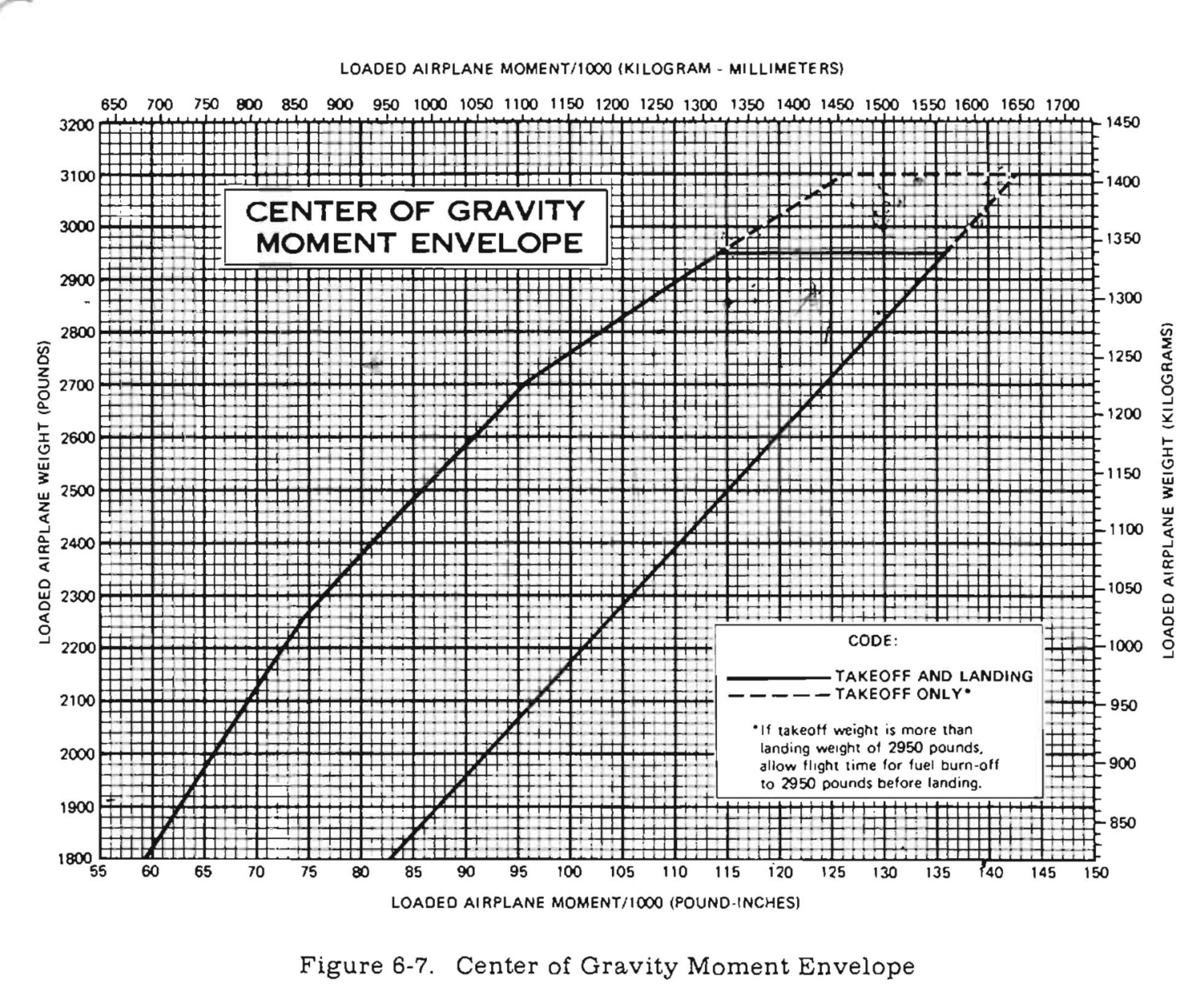
Weight and Balance
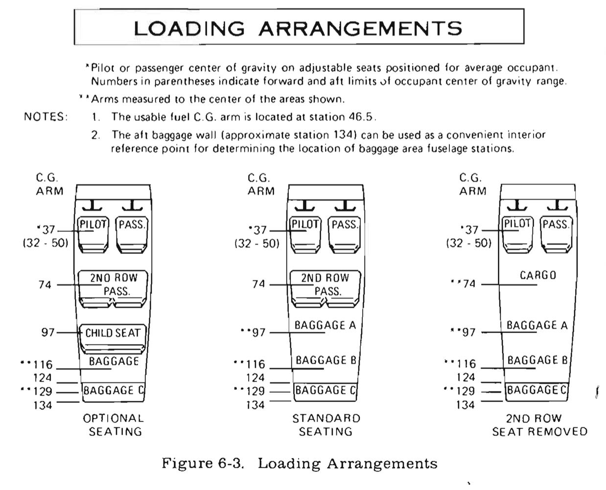
| Station | Weight | Arm (in.) | Moment (lbs.-inches / 1000) |
|---|---|---|---|
| Empty Weight | lbs | in. | 69.914 |
| Fuel (at 6 lbs/gal) | gallons | in. | 16.740 |
| Pilot | lbs | in. | 6.560 |
| Copilot | lbs | in. | 6.560 |
| Rear Passenger 1 | lbs | in. | 11.100 |
| Rear Passenger 2 | lbs | in. | 11.100 |
| Rear Baggage A | lbs | in. | 0.000 |
| Rear Baggage B | lbs | in. | 2.440 |
| Total Loading | 2907.10 lbs | 42.80 | 124.41 |
Applicable Recurring AD's
Serial #: 17261958
- 5/13/2011
- 2011-10-09
- 6/17/2011: Seat Rails and Roller Housing Inspections
- AD2020-18-01 - Lower wing strut attach point