Cessna 172N Overview
Structure
- Semi-monocoque
- Thru-spar construction
- Nose landing gear
- Oil/air strut, connected directly through the firewall
- Main landing gear
- Spring steel strut, very robust
- Hydraulic disc braking system
- Hydraulic lines have blue fittings
- Four seats
- Separate front seats, combined rear seat
- Shoulder harnesses and lap belts on front seats
- Two doors
- Windows, both openable on some models
Flight Controls
- Elevator
- Elevator trim
- Single trim tab on one of the elevators
- Ailerons:
- Frise-type ailerons, helps with adverse yaw
- Rudder
- Rudder pedals
- Cable actuated
- Single manual rudder trim tab
- Nose wheel
- Push-pull rods for ground steering
- Differential hydraulic brakes
- Flaps:
- Slotted flaps (Cessna calls them slotted-types flaps)
- Control lock
- Simple pin
- Rudder control lock also available
Powerplant
- Lycoming O-320, 160hp at 2700 RPM
- Horizontally-opposed, air-cooled, 4-cylinder engine
- Spinner is designed to direct airflow into the engine baffles
- Engine-driven magnetos
- Self-contained magnets that generate electrical sparks
- Induction system
- Air filter below the propeller, entire source of air for the engine
- Exhaust manifold which vents exhaust overboard
- The heater is a shroud around this exhaust manifold
- Updraft-type carburetor with a venturi
- Primer used for cold-starting
- Engine controls
- Carburetor heat for carburetor ice
- Throttle: controls airflow to the butterfly valve in the carburetor
- Mixture: red handle, controls fuel/air mixture
- Ignition switch
- Engine instrumentation
- Fuel gauges which are electric
- Oil temperature, oil pressure gauges
- Tachometer
- Oil system
- Wet sump oil system, all the oil is contained in the bottom part of the engine
- 6 quart capacity
- Use correct SAE viscosity temperature of oil
- Propeller
Fuel system
- Two tanks within each wing
- Fuel caps, one is vented one is not
- Fuel vent on left tank below the wing
- Tube between both tanks to allow venting between tanks
- Fuel sumps on both tanks
- Gravity-fed system into a fuel selector
- Fuel strainer on the gascolator at the lower point
Brake System
- Red hydraulic fluid which closes disc calipers on the rotors
- Parking brake, don't trust them
- If temperature increases while it's set can cause too much pressure to build in the system
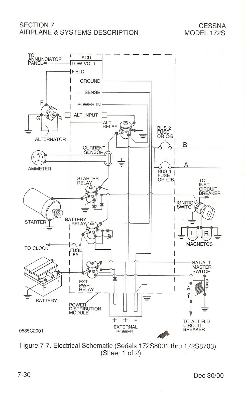
Electrical System

- Components
- 28V DC alternator (60A, continuous output)
- Higher voltage than the battery so it will charge the battery
- 24V, 14 A/h battery
- Without the alternator, the voltage should read 24V
- Provides 14 amps for 1 hour
- Bi-direction ammeter
- Over-voltage protection
- Hobbs meter: comes on with battery but is activated by an oil pressure transducer
Vacuum System
- Drive gyros to AI and DG
- Suction 4.2-5.5 PSI, suction gauge
Stall Warning System
- Mechanical reed that plumbs the sound into the cockpit
- Activated by low pressure at a certain threshold, given by a certain AoA
Static Wicks
- If you're going fast enough in precipitation you can build up static electricity on the control surfaces
- Static wicks are trailing wires that hang off the back which transmit the static off the back
